
| Step No | Action | Tool | Vendor | Notes |
|---|---|---|---|---|
| 1 | Mark sensor locations with Marker Pen |  |  | Locations will be advised by Strain Systems application engineering department |
| 2 | Drill the marked locations. | 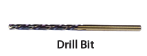 |  | Size #36 drill bit. Chicago Latrobe 550 Cobalt Steel Jobber Length Drill Bit, Gold Oxide Coated, Round Shank, 135 Degree Split Point. Hole must be drilled vertical to the surface. Use tap/drill guide |
| 3 | 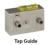 Use SSI’s Drill/Tap guide. |  |   | Apply WD-40 to drill bit and tap or other cutting lubricants available. |
| 4 | Clean the installation surface: Remove rust, paint. Use a grinding tip for the rotary tool. |  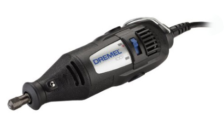 |   | Use any rotary tool such as Dremel to completely remove paint and rust. Surface should be shiny. |
| 5 | Polish and condition the surface. |  |  | Use the rotary tool with a fine sanding disk. Surface must be flat without any scratches. Use Dremel EZ413SA EZ Lock 240 Grit Sanding Disc |
| 6 | Finish the Surface. |  | This item is only provided by SSI. | Use SSI fine sanding disk and mandrel. Use with a drill. |
| 7 | Verify that sensor bolt runs through the drilled and tapped hole. Grease the surface to protect it from corrosion. |  |   | Use 6-32 x ½” Socket Head Cap Screw, black oxide for sensor mounting. Additional bolts can be purchased from other vendors. |
| 8 | Install and torque the sensors | Use a 25 lbs-inch torque wrench with the appropriate tip to install and torque the sensors mounting bolt |  | Make sure the sensor cable is vertical to the ground or to exerted force |
| 9 | Excite sensors individually and measure output | Use a 9 VDC battery to excite sensors. Use a voltmeter to measure output voltage between the green (signal+) and white (signal-) wires. | The output should be smaller than +/- 75 mV. If higher, there is an issue with the surface preparation. Uninstall and improve the installation surface. | |
| 10 | When all sensors are installed and tested, connect each sensor to a junction box & daisy chain all the junction boxes. The averaged output wire connects to the master junction box that connects to the electronics. For details, please see product manual and the videos on our web site or contact us at support@strainsystems.com | |||
| 11 | After all the system components are installed and the system calibrated, DO NOT forget to install the environmental covers over each sensor to protect them. Use Sikaflex sealant to attach and seal the covers. | |||
Note:
All items in the installation kit can be purchased from Strain Systems or customers can purchase the items through the provided links from other vendors.
Installation Videos